Before, we talked a lot about the configuration of switch, but still there are some don’t get well understood on them. Now, we show them in an interesting way.
Case 1, Assign VLAN to forbid the communication between two PCs in the same switch.
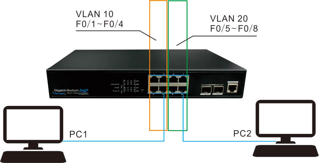
In our project, without any configuration, the two computers can access each other if they are connected to one switch at the same time. Shown as the picture. But if we assigned VLAN10 and VLAN20, the result would be different, as shown in the picture.

Here we provide an interesting example. If Jack and Rose are lovers, and they both work in the company A in the city Z, then they could date at any time as they want. In this example, the city Z is working as the switch, company A is the VLAN, and Jack and Rose are PC1 and PC2.
Since they are lovey-dovey in the company for many times, it has affected other single ones. And the company leaders have known the seriousness of this matter, so they decide to prevent them from meeting in the company. What should they do?
1. Requirement
In this project, it needs to isolate PC1 and PC2 in order to forbid the communication between them, which is also happening in a lot of projects. Then how do we configure it?
Whereupon, Jack is dispatched to the branch company B near the city to work, and that mean he is “isolated” with Rose. In other word, the branches work as the VLAN, we “isolate” Jack and Rose to different VLAN(branches), thus, they can not meet.

2. Set up VLAN
We can set up the VLAN 10 and VLAN 20 in following way according to the plan above.
Switch> enable // (Enter privileged mode)
Password: xxxx //(Input password)
Switch#configure terminal //(Enter global configuration mode)
Switch(config)#VLAN 10 //(Set up VLAN 10)
Switch(config-vlan)#name test10 //(Name VLAN 10 as test 10)
Switch(config-vlan)#exit //(Exit VLAN 10 configuration mode)
Switch(config)#VLAN 20 //(Set up VLAN 20)
Switch(config-vlan)#name test20 //(Name VLAN 20 as test 20)
Switch(config-vlan)#end //(Exit the configuration command and enter privileged mode)
Input “no vlan vlan-id” to delete the created VLAN under configuration mode
Switch(config)#no vlan 10 (Delete VLAN 10)
3. Add the ports of the switch to the specified VLAN.
Step 1
Add fastEthernet0/1~ fastEthernet0/4 to VLAN 10.
Switch#configure terminal // Enter global configuration mode
Switch(config)#interface fastethernet 0/1 // Enter the port configuration mode of fastEthernet0/1
Switch(config-if)#switchport access vlan10 // Add fastEthernet0/1 to VLAN 10
Repeat the above command and add the fastEthernet0/2 ~ fastEthernet0/4 to VLAN10 respectively.
Step 2
Add fastEthernet0/5~ fastEthernet0/8 to VLAN 20.
Switch#configure terminal // Enter global configuration mode
Switch(config)#interface fastethernet 0/5 // Enter the port configuration mode of fastEthernet0/5
Switch(config-if)#switchport access vlan20 // Add fastEthernet0/5 to VLAN 20
Repeat the above command and add the fastEthernet0/6 ~ fastEthernet0/8 to VLAN20 respectively.
4. Save settings
In order to prevent the loss of configuration parameters caused by power failure and other reasons, you can use the following command to save them after the configuration.
Router-A#write memory
or
Router-A#Copyrunning-config starup-config
After above operations, you can connect PC1 to the ports belonging to VLAN 10, and PC2 to the ports belonging VLAN 20. In this way, the PC1 can not PING PC2.
The configuration on the same switch is relatively simple. The basic idea is:
Enter configuration mode - Set up VLAN - assign ports to VLAN - then connect the associated devices (computers) to the corresponding ports. Basically, it makes use of the principle that ports between different VLANs cannot communicate directly.
+86-755-83898016-863
+86-1501-2669-765
[email protected]
Note: To speed up our service to you, please make sure the field with " * " mark is filled before you click on "Submit" button, Thank you!